Fixing Rangefinder & Smartphone Residual Compass (azimuth) Deviation Errors – True North
- Fixing Rangefinder & Smartphone Residual Compass (azimuth) Deviation Errors – Android & TruPath Compass (Evaluating “External” Devices & Apps)
- Fixing Rangefinder & Smartphone Residual Compass (azimuth) Deviation Errors – Android & TruPath Compass app (Repeatability Tests)
- Fixing Rangefinder & Smartphone Residual Compass (azimuth) Deviation Errors – Android & TruPath Compass app (Collecting Deviation Data)
- Fixing Rangefinder & Smartphone Residual Compass (azimuth) Deviation Errors – Android & TruPath Compass – Best Compass Calibration
- Fixing Rangefinder & Smartphone Residual Compass (azimuth) Deviation Errors – Android & TruPath Compass app (INTRODUCTION)

Row, row, row your boat gently up / down the stream???
Purpose: This blog is created to help readers a) better understand electronic compass [smartphone or rangefinder] residual azimuth deviation errors b) quantify the errors, c) model the errors, d) compensate for [correct] the errors, and e) influence their app vendor to apply the correction method within the affected smartphone app. Basically, we need to know (accurately) whether to go up / down the stream (path) we are traveling on.
- Problem Statement: Can rangefinders (with compass) and smartphone compass apps be made more accurate and more useful?
- Objective: Characterize and correct the residual compass azimuth deviation errors demonstrated by laser rangefinders and multiple compass apps operating on a single smartphone (iPhone).
In order to accomplish the objective and resolve the problem, it is necessary and sufficient to determine the character of the rangefinder/smartphone [iPhone] residual [after calibration] compass azimuth deviation errors by conducting actual (in-the-field) tests to a) measure the errors, c) model the errors, and d) determine the deviation compensation [correction] curves.
Background
We have all been exposed to the Apple Community, Google forums, and other forums in which users of smartphone compass apps have complained that their “compass does not work as expected”. Also, we’ve all seen the expert responses to “recalibrate the compass”. There are at least 7, 8, or 9 ways (published) to recalibrate. To be sure, recalibration of the compass does help; but it’s not the complete solution – by any means!
It is clear from published literature that the vendor’s (manufacturer’s) suggested calibration procedure applies directly to the placement of internal components and the magnetic fields they generate – primarily. Such calibration procedures may deal with environmental magnetic and/or electromagnetic influences which exist at a small distance from the compass; but not much is accounted for beyond that small distance – a few feet at best.
Also, it is clear from published literature that significant residual (after calibration) azimuth errors are present – again, caused by external environmental magnetic and/or electromagnetic influences within the work (use) environment. It is these residual azimuth errors that this blog will deal with exclusively to demonstrate a method for correcting azimuth error which cannot be dealt with by the vendor’s prescribed calibration procedures alone. In order to significantly improve the accuracy of electronic compass azimuth readings, a combination of a) the vendor-provided compass calibration procedure and b) a residual azimuth error compensation method must be used.
This blog will present an evolving set of case studies to illustrate a) the existing residual azimuth deviation error [magnitude & direction] demonstrated by multiple smartphone compass apps running on individual smartphones [iPhone & Android], b) the existing residual azimuth deviation error [magnitude & direction] demonstrated by multiple handheld laser rangefinders [with electronic compass], c) the practical error compensation that can be achieved, d) the deviation compensation curves themselves, and e) the ability to predict the residual azimuth deviation error.
Prerequisite: Establish True North & Principle Directions
The residual azimuth deviation errors can be determined by comparing successive compass azimuth measurements to True North and the remaining principle directions (NE, E, SE, S, SW, W, NW) – eight known directions. Since no existing compass is accurate enough to establish True North, the sun’s azimuth will be used to establish these benchmark directions – at a specific geographic position, on a given day, at a specific time of day. The tools and procedures for establishing the 8 baseline directions are as follows.
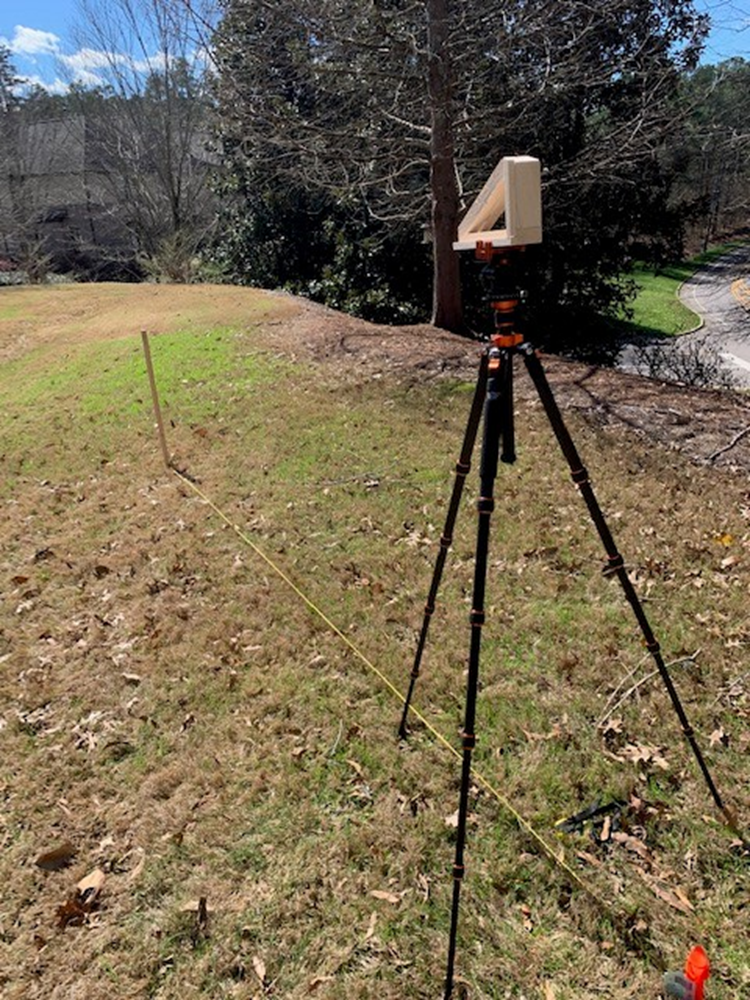
In these case studies, an easy and fast way of establishing True North is provided – to include the use of a solar azimuth-finding tool (mounted on the tripod in the photo). The solar azimuth is used to establish True North; because, it is a reliable entity that cannot be challenged.
Overall, the equipment consists of a) vertical [30 inch] stake, b) about 15’ of string, c) a tent peg, d) a non-magnetic camera tripod with an index [azimuth] ring, and e) a DIY solar azimuth tool. Either a) the vertical stake (with string/tent peg) or b) the solar azimuth tool could be eliminated – a personal preference; but in this case both tools are used for absolute confirmation. Note: A compass (no matter what type) cannot be used to establish True North; because a compass would introduce additional error – right from the get-go. The compass itself is in error!
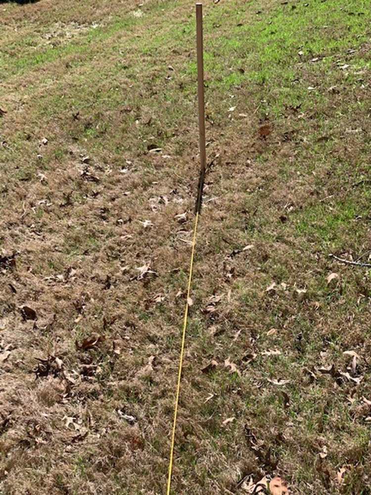
- Note that the string/tent peg are used with the vertical stake to make certain that the stake’s shadow is properly bisected and aligned with the tripod – quality assurance. Due to camera parallax, the vertical stake (shown in the previous photo) appears to be leaning; but it is not leaning.
- Note that, initially, the string/tent peg are positioned such that the shadow is offset from (not yet aligned with) the string. Since the shadow will rotate clockwise (northern hemisphere) over time, this construction technique allows time for the tripod to be properly positioned directly over the string.
With all the equipment in place, the time-of-day should be recorded when the stake’s shadow is bisected by (aligned with) the string. The date/time-of-day (along with geographic position – latitude) are needed to determine the sun’s azimuth using some reference material – documentation, smartphone app, etc. In these case studies, the iPhone app “Sun & Moon”/”Data Table” was used to provide the necessary date/time/sun azimuth information – after linear interpolation.
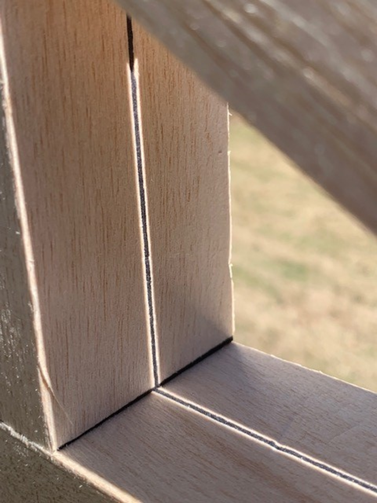
The proper alignment can be easily confirmed when the (redundant) solar azimuth alignment tool is used – as shown in the following photo. When properly aligned (with the stake/string), the tool allows sunlight to illuminate a scribed line within the tool. When not properly aligned, the tool prohibits sunlight from illuminating the scribed line within the tool.
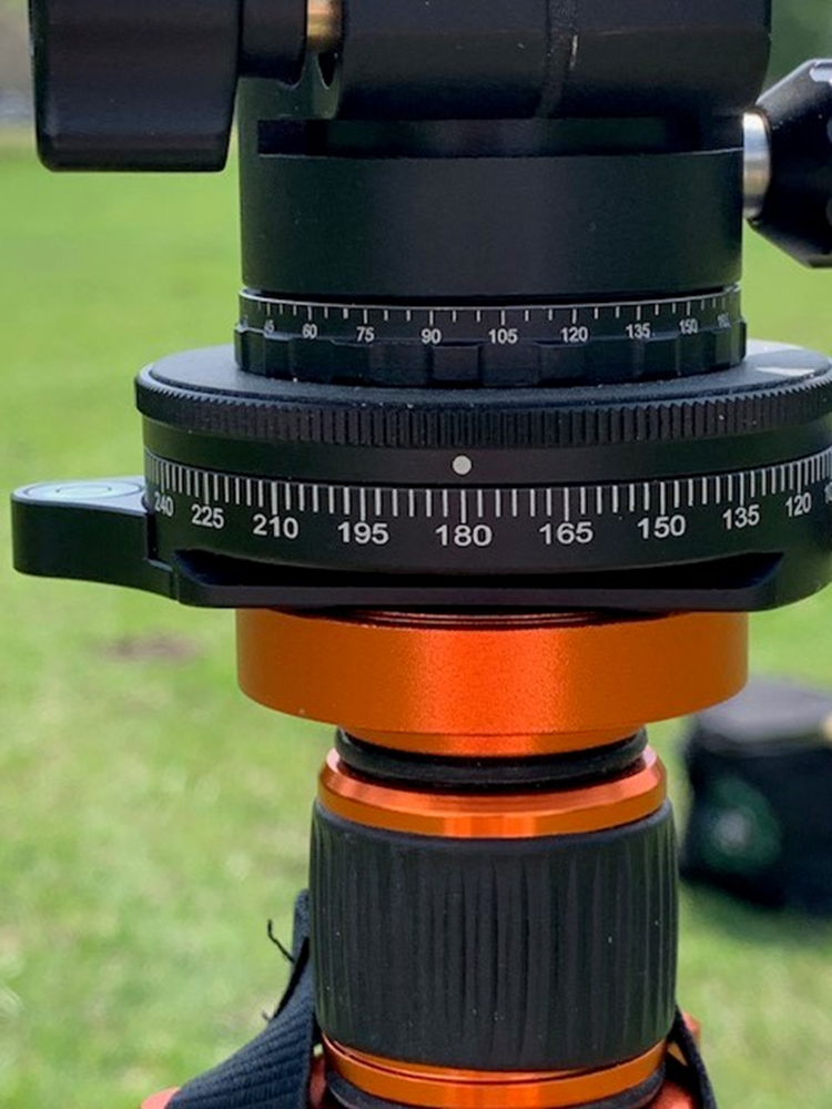
When proper alignment occurs (time-of-day), make careful note of the index on the azimuth ring of the tripod. This index reading (180) becomes the “base index” for using the index ring to a) find the True North direction as well as b) find the directions for all the remaining cardinal directions of the compass.
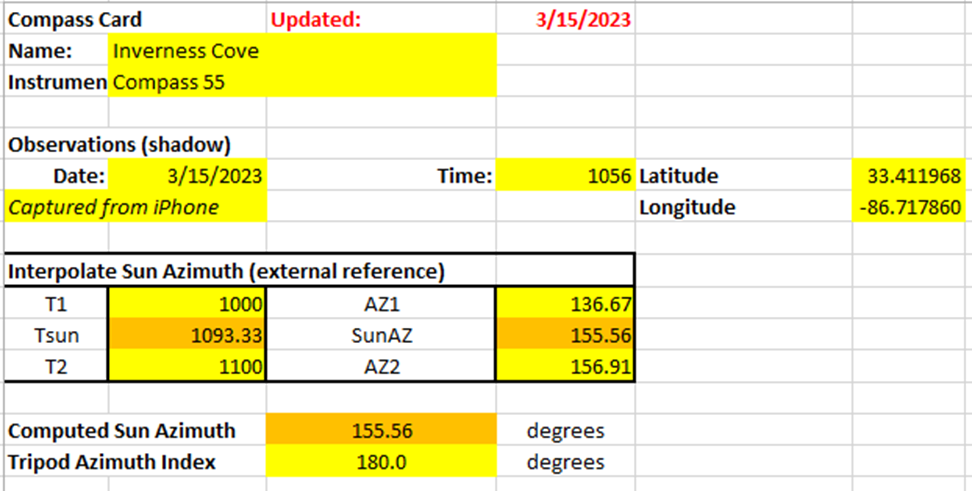
The following spreadsheet table illustrates the input/output of the process necessary to determine the sun’s azimuth. This data applies to all data collection activities.
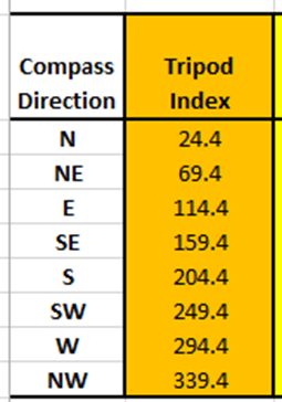
From the spreadsheet illustration below, note that the sun’s azimuth has been determined (interpolated using date/time-of-day/geographic position) to be 155.56 degrees. Subtracting the sun’s azimuth from the tripod’s base index value (for starters), we can see all the index readings we must use to locate the cardinal directions of the compass. First, rotate the tripod head counter-clockwise through 155.56 degrees (from the base index) to find True North (tripod index = 24.4). Next, rotate the tripod head clockwise (consecutively) to each indicated (below) index reading to position the tripod head correctly for the remaining cardinal compass headings – at each position/direction, smartphone compass readings [using a well-known app] will the collected/recorded.
Now that we have located all the cardinal directions of the compass, we can replace the solar azimuth-finding tool (on the tripod) with the rangefinder/smartphone to begin taking azimuth readings (first using the Vectronix rangefinder and then the compass apps) at each of the cardinal directions – for each orientation of the smartphone (horizontal, portrait, and landscape). Since we will be comparing compass azimuth results for multiple smartphone apps, we will be repeating the azimuth collection process (for each app chosen) using the same equipment setup arrangements and the same tripod index table used for the (first) Vectronix data capture operations.
To preview content of my next blog post, we will be rotating the smartphone/tripod head into and through each of the cardinal compass directions in order to a) collect compass azimuth readings and b) determine the deviation errors associated with each app of interest, direction, and smartphone orientation – as necessary. The Vectronix rangefinder data is collected first. Attention is given to capturing the “best” results provided by a) the Vectronix rangefinder’s electronic compass and b) the selected iPhone compass apps. Therefore, no “sighting” operations will be required during the data capture tasks: a) the sun’s azimuth was obtained as the basis for establishing True North and b) the indexed tripod head will be used [further] to determine the remaining principle compass (reference) directions.
After we have presented evidence that the residual compass azimuth deviation errors can be compensated quite well, the blog will present an even easier and faster method for obtaining the smartphone/rangefinder compass error measurements. You can look forward to this revelation.
Contact Us
“All truth passes through three stages. First, it is ridiculed. Second, it is violently opposed. Third, it is accepted as being self-evident.”
A WordPress.com site
